Why This Project?
This was my second 3D modelling project. I had a lot of fun experimenting SolidWorks features on my Cybertruck Jeep model. Having learned a lot from my previous experience and wanting to try something more advanced, I was inspired by Lego assemblies. Instead of 3D printing the gumball machine, I designed separate parts that could be assembled to create a 3D gumball. This project was designed for a group project, to create a 3D model involving the motif of a Canadian animal. My group decided to design a gumball machine in the shape of a squirrel, hence the head and tail parts. Spanning over a month and a half, I enjoyed the process of creating something new, and learning about locking mechanisms to keep the different parts in place.
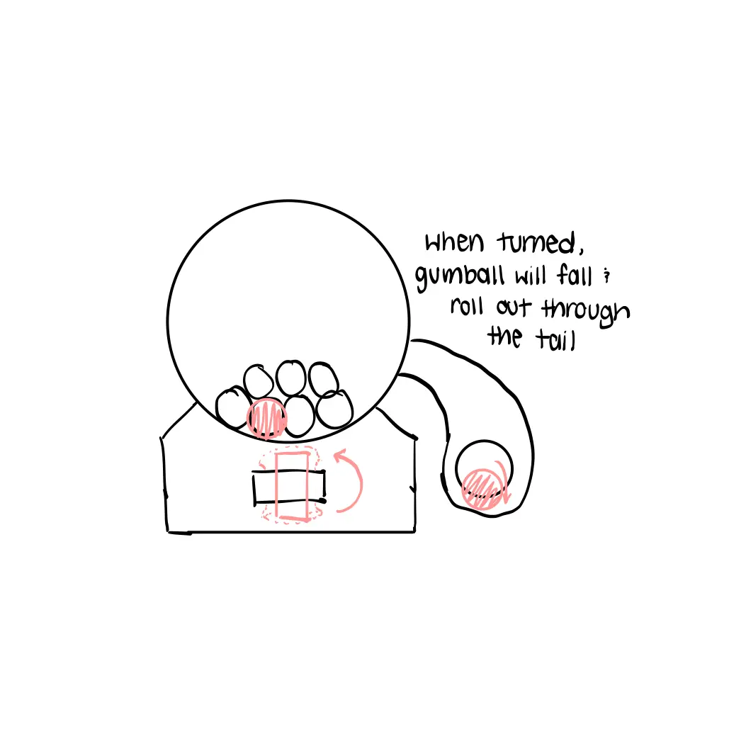
Concept & Struggles
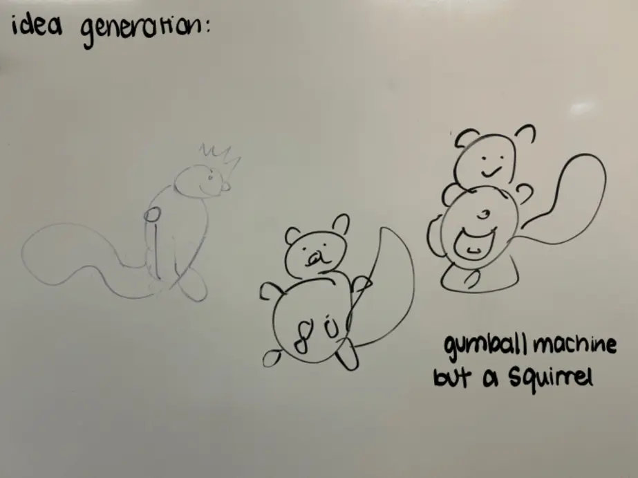
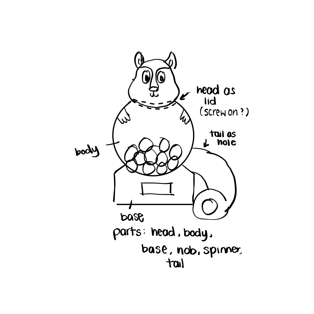
The idea was a squirrel shaped gumball machine. Unscrewing the head will allow a gumball to be inserted into the body of the squirrel. The gumball will drop through the body into the container of the machine where it will be caught in the spinner. The crank will need to be spun to funnel the gumball out of the container and in the tail, where it enters the final stage of its journey, spiraling down and exiting out of the machine, when it can then be eaten.
Container
Concept / Struggles
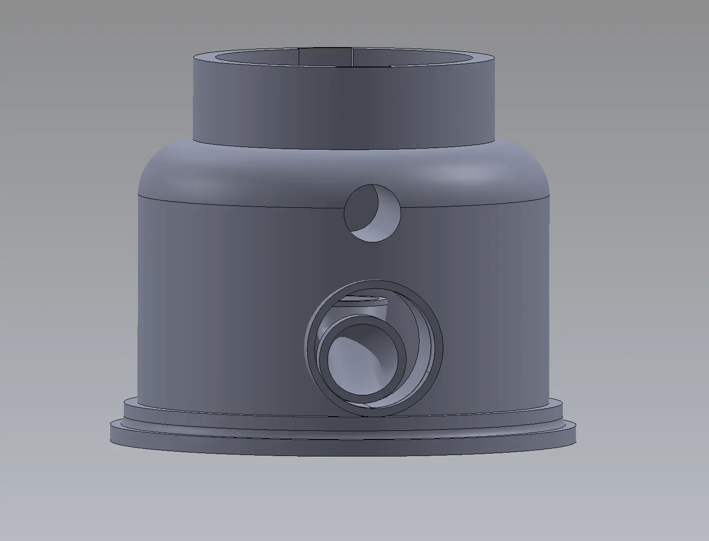
Initial Container Concept
The container served the purpose of funneling the ball from the spinner to the tail. The container was the main component of the build, mainly because the spinner, crank, body, and tail, needed to inserted. The original design of the container (picture above) had a tunnel that connected the entrance from the body opening to the exit that connected the tail, but we faced a lot of printing errors, resulting in the printer refusing to print our model. In theory, our idea would work, but it wasn't very practical in terms of printing, because there was nothing supporting the tunnel. We attempted to print the model multiple times, and it did print one time, but it was very difficult to remove the filling inside the tunnel. We devised a new idea, to guide the ball as it fell, and using its momentum to leave the container. This method proved to be much better, with the only downside being that it took a lot more ink to print, but it was more efficient and provided a smoother journey for the ball. You can view the inside of the container by zooming into the model above and adjusting the camera to see where and how the ball moves.
Body
Concept / Struggles
Initial Body Concept
The body of the gumball machine was to hold the balls before they can enter the spinner and go down the container. It's main aesthetic purpose was so that the squirrel would have a realistic body, similar to how squirrels save acorns in their mouth, this one saved gumballs in its stomach. It connected the head and the container and had two different locking mechanisms for each side, since the diameter of the head and the container were different. They were both a snap-fit locking mechanism, where the pieces had to be placed in their respective slots and rotated to lock so they wouldn't fall apart.
The main struggle I faced with this part was designing the body proportions so it looked like a realistic squirrel. Initially, the plan was to hold multiple balls in the body, so we had kept the space open, and sized down the tunnel to the container, so all the balls don't fall in. We realized after assembly, that the body was either too small, or much larger than the rest of the pieces, so we scaled them to be visually authentic.
Crank
Concept / Struggles
Initial Crank Concept
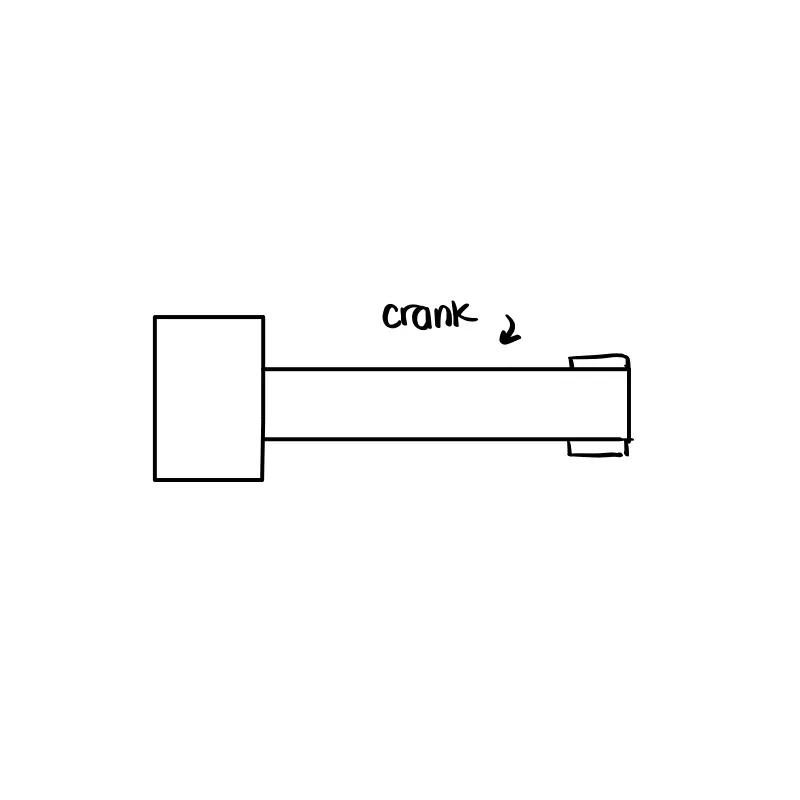
The crank was fairly simple to design, with only a few sketches, extrudes, and fillets. The design behind it was to mimic a key, to enter the slot of the spinner so it can be turned. I added fillets to the handles for safety reassurance to avoid sharp edges.
Another issue with the spinner happened post printing. Although the crank and spinner fit in the original design, we underestimated the tolerance for fitting. We had initially kept it at 0.1 mm, but the crank still wouldn't fit into the spinner. It taught us a good lesson to check the tolerance for various 3D printers, since we used multiple printers and the fitting was inaccurate sometimes because they were printed from different machines. Sanding the crank down seemed to do the trick just fine.
Spinner
Concept / Struggles
Initial Spinner Concept
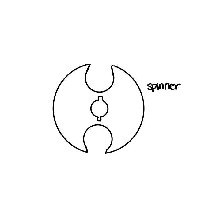
The spinner had curved slots where it would hold the ball. With my limited knowledge of 3D modelling, I wasn't sure how I would design that. However, I was familiar with an extrude method to create a rectangular sketch and extrude cut it. To allow a smoother fit of the crank into the spinner, we decided to add chamfers in the slot for the spinner to ease its way in.
Another issue with the spinner happened post printing. Although the crank and spinner fit in the original design, we underestimated the tolerance for fitting. We had initially kept it at 0.1 mm, but the crank still wouldn't fit into the spinner. It taught us a good lesson to check the tolerance for various 3D printers, since we used multiple printers and the fitting was inaccurate sometimes because they were printed from different machines. Sanding the crank down seemed to do the trick just fine, instead of printing the piece again.
Head
Concept / Struggles
Initial Head Concept
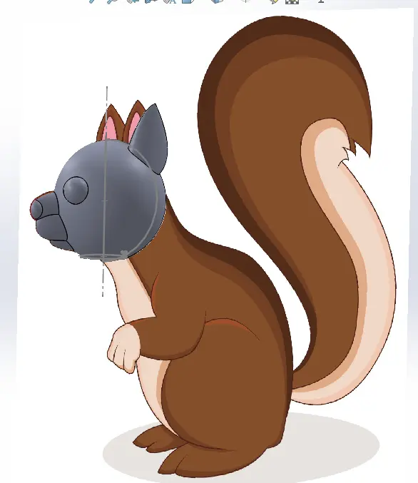
For the head, there was a lot of ideas of designing a face with ears, a nose, eyes, and a mouth, but we faced a lot of technical SolidWorks issues working on it. Initially, I wanted to sculpt a detailed face to give the model more personality, but SolidWorks' surface modeling tools were challenging to use effectively with my skill level at the time. I tried to use lofts and boundary surfaces to create smooth facial contours, but getting the transitions between the different features to blend naturally was difficult. The software would sometimes generate errors from self-intersecting surfaces, which made the process frustrating. We kept a simple design for the face to disregard these issues.
Another significant issue was ensuring that the head could be securely attached and removed for refilling the gumball machine. The initial plan was to use a screw mechanism, but threading a cylindrical piece in SolidWorks required precision, and it was difficult to match the same pattern on the body to connect to the head. I considered using a snap-fit design instead, which would ensure it would remain secure and still be removable simplified our solution. Cutting a slot for the head to turn and snap into was the design and it worked out well, so simply lifting the head would not dislocate the piece, it would need a bit of maneuvering to remove.
Container
Concept / Struggles
Initial Tail Concept
In the concept sketch, the tail was inserted into the model at the back for decoration, and funneling out of the container would land the gumball outside. But to improve the contribution of each piece to the build, we decided to use the tail as a helix spiral to ramp the ball down. Next, near the end of the tail, you can see the top of the tail is uncovered. This was an adjustment we added after printing our draft pieces. When 3D printing, hollow pieces will be drawn with a filling inside. It was difficult to remove the filling with the entire tail covered. Leaving a portion of the top uncovered didn't compromise the design and allowed us to take some pliers and pull the filling out.
What did I learn?
This project taught me lessons in 3D modeling, problem-solving, and practical design adjustments. A crucial challenge was learning to navigate SolidWorks' surface modeling tools, as sculpting organic shapes like a squirrel's face often resulted in self-intersecting surfaces, broken constraints, and undefined sketches. Designing smooth transitions between the ears, nose, and head required multiple iterations, and even small modifications sometimes caused unexpected errors in the model tree. Another difficulty was managing complex assemblies, making sure that different components, such as the head, body, and container, fit together without interference while still allowing for proper movement.
Tolerance issues became apparent after printing, as even small discrepancies between 3D printers affected how the crank fit into the spinner and how the body fit in the head and the container, teaching me the importance of accounting for material shrinkage and printer variability. Additionally, creating functional mechanisms like snap-fit joints and rotating parts required precise alignment, and I had to experiment with different clearances to ensure they worked correctly without being too tight or too loose. The initial design of the container failed multiple times due to unsupported tunnels, leading to printing errors and difficulties removing internal supports, forcing us to rethink and redesign our approach.
Learning how to create a helical ramp for the tail was another challenge, as SolidWorks' helix tools can be unintuitive, and aligning it with the rest of the model required careful constraint management. File organization also became an issue, as a project with multiple interdependent parts required a structured approach to avoid broken references when making changes, and working on multiple iterations of different parts made it difficult to keep track of the most updated versions. These challenges taught me the importance of iterative prototyping, careful planning, problem-solving around technical and design issues, and adapting to real-world limitations, ultimately making this a project that I'm proud to display to the world, showing my abilities in 3D modelling.
To showcase my learning, you can interact with my gumball machine model above and view all SolidWorks parts and assembly instructions on my GitHub.